Arduino 5 Fading an LED
- Erika Camilleri
- Dec 27, 2022
- 4 min read
Updated: Jan 23, 2024
So far we have only worked with digital input and outputs. In this lesson we will learn to work with input and output that has a range or is continuous which ultamtely means that it will be analog.

Analog versus Digital Data
We already discussed these types of data in Chapter 3. Let us look back on what we said.
We have only worked with digital values by making use of the digitalWrite() command. An LED on our circuit board was either HIGH (on) or LOW (off).
  digitalWrite(4,HIGH); // turn led on
  digitalWrite(4,LOW);  // turn led off
We interact with a world which is physical and real life is not as simple as on or off. A metal rod that is getting heated is not cold and then instantly gets hot... it gets warmer and warmer over a period of time.
We need our computers to be able to take in precise input and give us precise feedback.

In this lesson... 📝
Make use of analog output components by programming an LED fade.
Make use of analog input components by taking potentiometer readings.
Use standard code libraries to simplify complex functions.
Using the Serial Monitor to log events so that we can closely monitor what is happening.
Analog Output Pins
Maker UNO has some special PINs that support analog output data. You can see identify them from the ~ symbol next to the pin reference. Look at the board and notice pins with a ~ next to it, for example, ~3, ~5, ~6, ~9, ~10, ~11 are highlighted in red in the image.

When we need to output something as analog, we need to use one of these pins. We will demonstrate this using a fading LED light.
To be able to set different values for ON we need to use the analogWrite() command.
analogWrite(5, INSERT_LED_VALUE); // led value can be between 0 and 255A circuit and program that gives analog output

Use the following code to see how the behaviour of our output component changed!
// variables used by all the program
bool isSignal = false;
int LEDLIMIT = 255;

void setup()
{
  pinMode(5, OUTPUT); // led analog
  pinMode(3, INPUT); // push button
}

void loop(){
  if(digitalRead(3) == LOW) { // press push button
    isSignal = !(isSignal);   // ! is the NOT gate
  }

  if (isSignal) {
    analogWrite(5, LEDLIMIT ); // max 255
    delay(500);

    analogWrite(5, 100); // decrease to 100
    delay(500);

    analogWrite(5, 0); // decrease to 0
    delay(500);
  }
}
Breaking down the code
By looking into the code closely we notice that:
Nothing has changed when declaring our output pin using pinMode(). We just need to make sure to pick an analog pin, in this case we chose pin ~5.
The push button controls when the fading starts. We're very familiar with pushbuttons now.
The analogWrite() takes two input variables: the pin, and an integer that represents some analogue value between the min and max supported by the component. LED components support values between 0 and 255.
First, we call analogWrite() to first switch the LED on to FULL BRIGHTNESS (255). Then we set it to 100, and finally we set it to 0, which in reality is equivalent to the digital LOW.

Reverse It Challenge!
Why not try to update the code to make your LED go back up to the MAX value of 255 after having gone down?
Analog Input Pins
We will be replacing our push button with an analog input device called a potentiometer.
The pushbutton is a digital input device, because a button is either ON or OFF.
A potentiometer allows us to get an analog input, where the input varies based on how much the potentiometer is turned.

We will use special pins that are dedicated to analog inputs on the Maker UNO X, which are called using the analogRead() command. The potentiometer uses 3 wires: one for the live, one for the ground, and another connected to one of the analog inputs on the board.
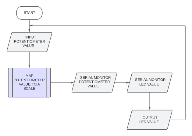
We will write a program that takes a reading from the potentiometer to control the brightness of an LED. To do this we will use the library function map(), which helps us scale input values within a certain range, to output values in another range. The potentiometer has an input value range of 0 to 1023, while the LED has an output value range of 0 to 255, as we saw previously. We will also output the values of our variables to the Serial Monitor to make sure everything is working as expected. All of this is explained in the flowchart hereunder.

A circuit and program that accepts analog input

Use the following code to see how the behaviour of our input component changed!
// variables used by all the program
int LEDLIMIT = 255;

void setup()
{
  Serial.begin(9600); // console output
  pinMode(5, OUTPUT); // led
}

void loop()
{
  // read the analog input from the potentiometer
  int potentiometer_value = analogRead(A0);

  // use map to scale input from the input range to the output range
  int led_scaled_value = map(potentiometer_value,0,1023,0,LEDLIMIT);

  // log some output so that you can realise what is happening
  Serial.println("Potentiometer input: ");
  Serial.println(potentiometer_value);
  Serial.println("Led output: ");
  Serial.println(led_scaled_value);

  // write analog output to the led
  analogWrite(5, led_scaled_value );
  delay(1000);
}
When you turn the potentiometer up and down, you should see the LED fade accordingly!
Outputting values to the console using Serial
In the previous example, we used the Serial syntax to keep track of the potentiometer reading and the mapped value of the LED. This allowed us to monitor our program closely and make sure the components are working as they should.
To make use of this useful tool in your code do the following:
In setup, declare Serial.begin(9600); to enable use of the Serial Monitor.
When wanting to output something to the Serial Monitor, use Serial.println() passing a "text in double quotes" or a variable to output.
On Tinkercad, you can access the serial output using the Serial Monitor expander at the bottom of the screen while you are running your simulation.

In the Arduino IDE you can navigate to Tools > Serial Monitor.


Comments