Arduino 3 External Input Components
- Erika Camilleri
- Jul 13, 2022
- 5 min read
Updated: Jan 6, 2023
Up till now we have only hooked up LEDs as external output components using the breadboard. Next on our list is to hook up an input component using the breadboard. In this post we will hook up a simple push button into the circuit. We will also take a closer look at the components.

Glossary
Breadboard | A device used to design and test electrical components in an electric circuit. |
Polarity | A way of saying that an electric component has opposing physical properties at two ends so that an electric current can only flow in one direction. |
Positive | An electric charge that has more protons. |
Negative | An electric charge that has more electrons. |
Rail | The horizontal rows on a breadboard that supply power. |
Terminal | The vertical columns on a breadboard that is connected to the GND source. |
Getting familiar with our electric components

Breadboard
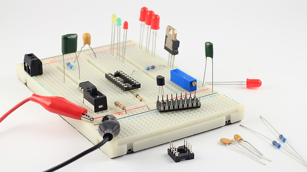
The main reason why we can construct a circuit quickly on the Maker Uno X is because of the breadboard. This device is used in the early stages of designing electrical products. These boards have holes so that electrical components can be easily pushed into them to allow current flow without permanently welding things together on a printed circuit board. This is convenient as it allows us to swap components quickly whilst we learn about circuits. The short video here 👇 is a big help to learn more.
Jumper Wire
A jumper wire is a single electrical wire with pins at each end that can slot into the holes of a breadboard helping us form closed circuits without welding components.

Resistor
We already touched on this in the previous lesson, but we will get into a bit more detail here.

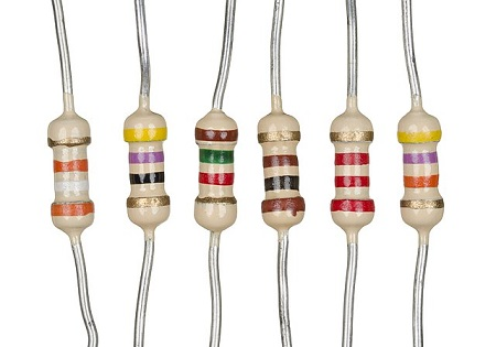
Recall that a resistor is the component that controls the flow of the current. These devices make it harder for electrons to pass through so that less charge can be absorbed by input/output components in our circuit. You can control how difficult it should be for current to flow by selecting the type of resistor indicated by the different colour bands. You may use this online calculator to get the value of resistance in ohms. A higher number means a higher resistance. A simple experiment with an LED can demonstrate the effect a resistor can have. You should notice that certain resistors will significantly reduce the brightness of a bulb. Try it out!
Diode
We build circuits so that electricity can flow into components that are useful to us somehow. The most obvious example is a small LED which we did program in previous lessons, when electricity flows through the bulb then a faint light glows. At times, a more generic term is used for these components: diode. An LED is one type of diode, to explain, it is an electrical check valve with two terminals, positive and negative, allowing current to flow in just one direction. It should be easy for us to tell which terminal is positive which needs to be aligned with our live jumper wire (I like to use a green wire). In the case of an LED the longer leg is positive.

Other Components
Push button
LED display
Servo motor
Ultrasonic sensor
In this lesson... 📝
Use Tinkercad to write a program that will make an LED act like a timer by introducing variables.
A circuit with a light and an external push button from the Arduino Learning Guide.
Make an LED act like a Timer
Say hello to Tinkercad 👋
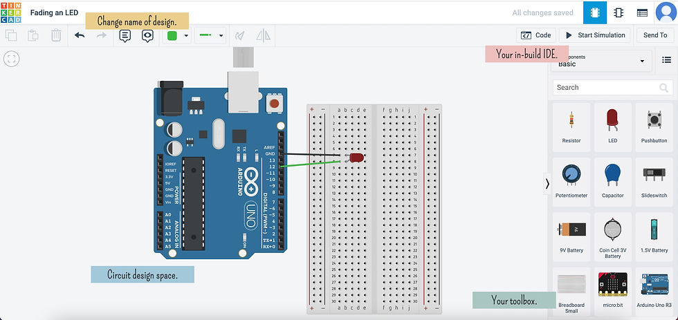
We will explore a useful study tool named Tinkercad, which is a coding playground for electric circuits. Rather than building a real circuit, we will use this design tool so that you can get an idea of how you are meant to study for your coursework in your own time. Follow these steps to get started:


When you open the Code Editor you should see some boiler plate code. I amended it slightly so that pin 12 is set to OUTPUT mode. This is enough code to make sure the circuit is setup correctly. When you click on Start Simulation you should see the red light flash.
TIME to program our LED ⌛
Pun intended 🙂.
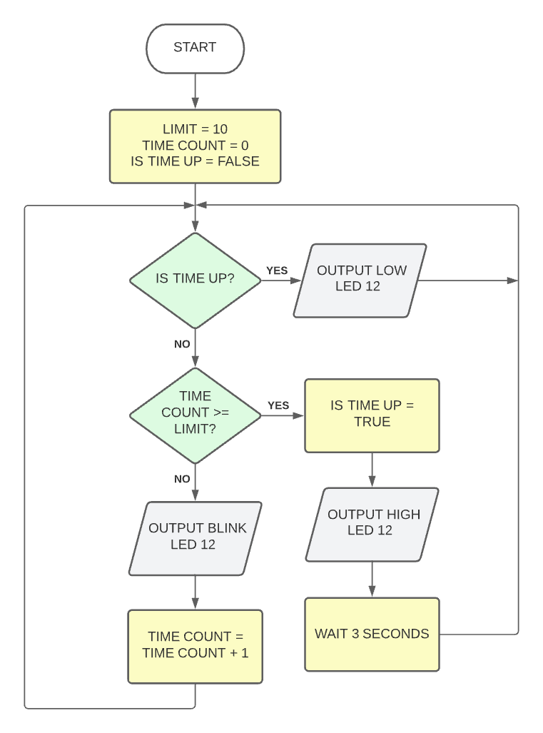
We would like our LED to blink steadily to indicate that time is running out until finally time is up! When the time is up the LED glows steadily for a couple of seconds before switching off completely. Let's visualise this concept by drawing a flowchart.

You should notice that we declared some data, included conditional statements and performed some basic arithmetic. A kind reminder to refer to Chapter 51 if these concepts are still unfamiliar.
Declaring the data we need is easy to do in C++. It is important to declare them at the very top of the program!
const int LIMIT = 10; // const means it does not change
int timeCount = 0; // type variableName = val;
bool isTimeUp = false;
The logic inside the loop method can look a bit more interesting and make use of the information we are storing like so...
void loop ()
{
    if (isTimeUp == true) {
        digitalWrite(12, LOW);
    } else if (timeCount >= LIMIT) {
        isTimeUp = true;
        digitalWrite(12, HIGH);
        delay(3000);
    } else {
       // ... code to blink LED 12
       timeCount = timeCount + 1; // incrementing timeCount
    }
}
Variables and Constants
Being able to store data in our programs is essential. Data that can change in an algorithm is called a variable, but you can also have data that remains constant.
In our programs, we can declare pieces of data as long as we know what type of data it needs to store.
We can also assign appropriate values to our pieces of data. It is very important to name our data items appropriately.
int totalScore = 12050; // integers or whole numbers eg. 1, -2, 546

double temperature = 23.4; // real numbers eg. 1.3, -5.7, 23.45

char currentPlayer = 'A'; // single characters eg. 'a', 'A', '!'

string state = "GO"; // text with multiple characters e.g. "Bob"

bool isTimeUp = false; // boolean stores only true or false
Hooking up an External Push Button
We will be enhancing the circuit above so that our LED timer can start on a push of a button. Have a close look at the following circuit diagram and set it up yourself slowly. Always double check to make sure your physical circuit looks exactly like the image below.

Here is what you will need:
Use the push button to trigger the timer
We only want to make minor adjustments to our existing timer code so that the timer can start on demand. We already need learned code that helps us read a digital input in the previous lesson. Lucky for us, reading an external input component is similar.
digitalRead(PIN_NUMBER); // must go in the setupAs in previous lessons, make sure to declare all input/output elements in the setup.
Below is the entire solution in full. Go through it very slowly and try to break it down. We have also left some simple TODO exercises for you to make the result more interesting.
const int LIMIT = 10; // const means it does not change
int timeCount = 0; // type variableName = val;
bool isTimeUp = true;

void setup()
{
  pinMode(13, OUTPUT); // led timer
  pinMode(3, INPUT);   // push button
  // todo add buzzer output
}

void loop()
{
 	if (digitalRead(3) == LOW) { // press push button
  		isTimeUp = false;
  	}

    if (isTimeUp == true) {
        digitalWrite(13, LOW);
        timeCount = 0;
	} else if (timeCount >= LIMIT) {
    	    digitalWrite(13, HIGH);
         // todo use buzzer
    	    delay(3000);
        isTimeUp = true;
	} else {
	    digitalWrite(13, HIGH);
	    delay(1000);
	    digitalWrite(13, LOW);
        delay(1000);
        timeCount = timeCount + 1; // incrementing timeCount
	}
}

Comments